I was doing a bit of experimenting with an old router I had lying around and there came a call for a USB to TTL adapter to read the serial port of said device. It was actually a UART port I wanted to read.
I looked around on eBay and they weren’t expensive but then I remembered I had an old Arduino Yun laying about the place. Being a tight Yorkshire man, I decided to do some digging!
Once I cast my mind back and remembered how to use it again, I connected it by USB to my PC and installed the Arduino Create plugin. There are some examples of serial connections already pre-loaded so decided to take a look.

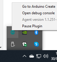

Once you have Arduino Create installed (link here: https://create.arduino.cc/ ) you should have the icon in your taskbar. Right-click it and left-click ‘Go to Arduino Create’.
You will need an account, but I’m guessing you’ll have one already, if you have the Yun. So, register or login and click on ‘Arduino Web Editor’.
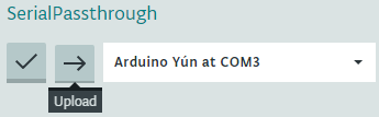
Now, make sure you are connected to your Yun by looking at the following, near the top of the editor window:

If it isn’t showing a connection on a certain COM port, make sure you have the drivers installed, although this should be done automatically on Windows 10. To check this, head to Device Manager (Press Windows Key  & R to open ‘Run’ then type devmgmt.msc and press the Enter key).
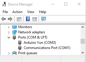
Expand the ‘Ports (COM & LPT)’ listing by clicking the right-pointing arrow and you should see something similar to the above. The above shows my Arduino Yún is connected to COM3. This is the connection that should be made in the Arduino web editor. If you don’t have this showing, try and update the drivers by right-clicking the COM port your Arduino is showing on and choosing ‘Update driver’.
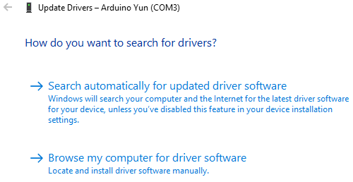
Click on the first option, ‘Search automatically for updated driver software’ and let the Internet do the rest. Your Yún should now show as ‘Arduino Yun (COMX)’. X being your chosen COM port by the free order of COM ports on your PC.
Whilst discussing Device Manager, we can see the settings of the COM port by right-clicking the Arduino’s COM port and selecting ‘Properties’ and then the ‘Port Settings’ tab.
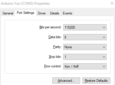
The ‘Bits per second’ field is the speed in which our serial port will communicate at. You will either know this by documentation of the device you are trying to read or by trying different ones. Don’t worry, there is no harm in experimenting! All that will happen with the incorrect setting is you will proabably get garbled symbols and squiggles instead of text when you connect to the device you are trying to read by UART, TTY etc.
The other settings are normally left at the default shown in the picture. That is, ‘Data bits: 8, Parity: None, Stop bits: 1, Flow control: Xon / Xoff’. I have had to use Flow control: None but the rest I have never had to fiddle with.
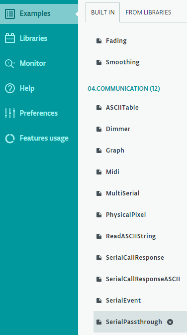
By now, we should have a lovely connection to our Yún in the Arduino Web Editor page. Click the ‘Examples’ tab on the left and then expand the ‘Communication’ section. Select ‘SerialPassthrough’.
/*
   SerialPassthrough sketch
 Some boards, like the Arduino 101, the MKR1000, Zero, or the Micro, have one  hardware serial port attached to Digital pins 0-1, and a separate USB serial port attached to the IDE Serial Monitor. This means that the "serial passthrough" which is possible with the Arduino UNO (commonly used to interact  with devices/shields that require configuration via serial AT commands) will  not work by default.
 This sketch allows you to emulate the serial passthrough behaviour. Any text  you type in the IDE Serial monitor will be written out to the serial port on  Digital pins 0 and 1, and vice-versa.
 On the 101, MKR1000, Zero, and Micro, "Serial" refers to the USB Serial port attached to the Serial Monitor, and "Serial1" refers to the hardware serial port attached to pins 0 and 1. This sketch will emulate Serial passthrough using those two Serial ports on the boards mentioned above, but you can change these names to connect any two serial ports on a board that has multiple ports.
 created 23 May 2016
   by Erik Nyquist
*/

 void setup() {
   Serial.begin(9600);
   Serial1.begin(9600);
 }
 void loop() {
   if (Serial.available()) {      // If anything comes in Serial (USB),
     Serial1.write(Serial.read());   // read it and send it out Serial1 (pins 0 & 1)
   }
You will see the Sketch above in the right-hand editing panel. If you attempt to edit this example you will have a dialog box appear, similar to the one below:
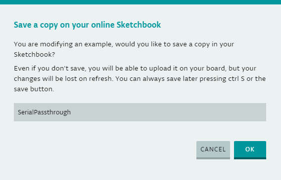
Simply type some text on the end, or change it to something that is more memorable to you for the device you wish to connect to. You could call it ‘cock-womble’ for all it cares. As long as you know what it is for, as the sketch will be named that going forward.
I know the device I wanted to connect to has a BAUD rate of 115200, so after I renamed my sketch I went ahead and changed the Serial.begin(9600); and Serial1.begin(9600); to be both 115200 instead. Serial is the USB port and Serial1 is the TX and RX pins of the digital side of your Yún device. If you are really bored, or really interested in these rates, then more can be found here https://en.wikipedia.org/wiki/Serial_port#Data_bits
Once you have set the BAUD rate or are happy with the default, you need to upload this sketch to the Yún. Simply click ‘Upload’ to do this.
The importance of what we have just done with this simple sketch is thus:
Any serial activity on the USB port (connected to your PC) is also passed to the TX and RX pins of the Yun, but ALSO, any activity on the TX and RX pins of whatever is connected to the Yun, gets passed to the USB port connected to your PC. This way, we can start a serial connection, using PuTTY for example, to see what is going on!
If that didn’t make sense, read it again, you idiot! Only joking… In simple terms, we now have a bi-directional connection from the PC to the serial port of the device we have connected the Yun to. Everything that passes through either end will be received and transmitted to both devices.
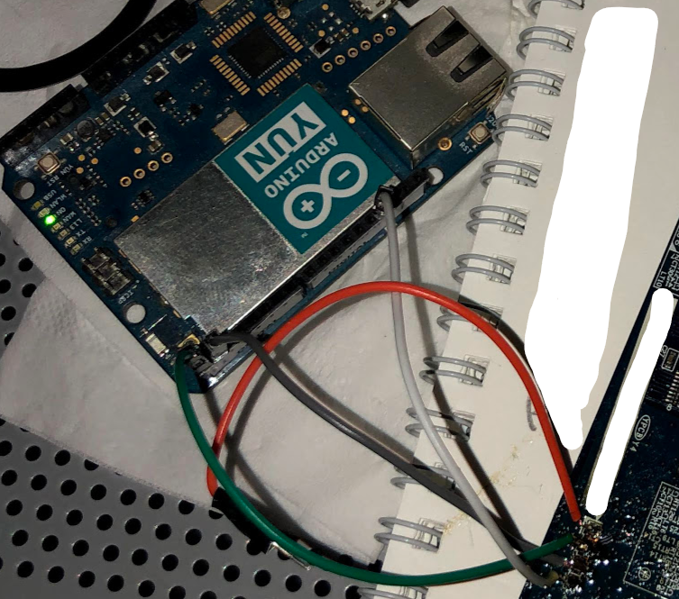
With that said, we now have to connect our TX, RX and GND pins to our serial or UART device. The devices normally have a 4 pin layout of V++ TX RX GND. Many times, the V++ pin is not required and will infact stop all communication if connected.
I have also had circumstances where if one of the TX or RX pins are connected before the device is powered on will cause no communication. Be patient and try different things if you don’t get a result the first time. If you get anything, be it garbled lines of crap scrolling across the screen, simply try and swap the TX and RX lines. You ARE getting closer to a result.
OK, so we’re nearly at the end of our adventure! Let’s hook this baby up to power and see what we get…
If you haven’t already got it, head over to https://www.chiark.greenend.org.uk/~sgtatham/putty/latest.html and grab PuTTY for your operating system and install it. Once opened, you will see many options. Don’t fret, all we have to do is gather the information you have already learned from this tutorial and feed them in.
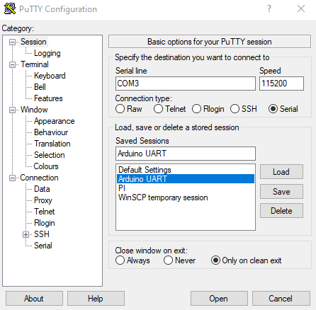
Firstly, select ‘Serial’ from the radio options under ‘Connection type:’ and then type in the COMX port we grabbed from the Device Manager in the ‘Serial line’ field. Then, type in the BAUD speed that your device is capable of. If you don’t know it, start from 115200 and then work through the options you aquired from viewing the Device Manager port settings for the COM port your Arduino is connected to. Finally, click ‘Open’ and a black screen will open. You will hopefully see data when your device is powered on.
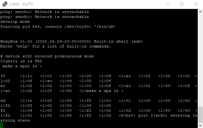
There we have it! Human-readable text from a serial connection!
The awesome thing about having both RX and TX pins connected is, we can also send commands using PuTTY like Ctrl-C (^C) etc. to interface with a bootloader. The possibilities are varied if you put your mind to it. If you get no response even though the output is telling you what to press, it may just be that the manufacturers of the device have disabled it. At least you tried!
I hope this has helped somebody. If it has, I really would appreciate a quick comment or feedback on where I can improve. For now, see ya’ later guys! Dave.
No responses yet